An Overview of Link Aggregation and LACP
The concept of Link Aggregation (LAG) is well known in the networking industry by now, and people usually consider it as a basic functionality that just works out of the box. With all of the SDN hype that’s going on out there, I sometimes feel that we tend to neglect some of the more “traditional” stuff like this one. As with many networking technologies and protocols, things may not just work out of the box, and it’s important to master the details to be able to design things properly, know what to expect to (i.e., what the normal behavior is) and ultimately being able to troubleshoot in case of a problem.
The basic concept of LAG is that multiple physical links are combined into one logical bundle. This provides two major benefits, depending on the LAG configuration:
- Increased capacity - traffic may be balanced across the member links to provide aggregated throughput
- Redundancy - the LAG bundle can survive the loss of one or more member links
LAG is defined by the IEEE 802.1AX-2008 standard, which states, “Link Aggregation allows one or more links to be aggregated together to form a Link Aggregation Group, such that a MAC client can treat the Link Aggregation Group as if it were a single link”. This layer 2 transparency is achieved by the LAG using a single MAC address for all the device’s ports in the LAG group. The individual port members must be of the same speed, so you cannot bundle for example a 1G and 10G interfaces. The ports should also have the same duplex settings, encapsulation type (i.e., access/untagged or 802.1q tagged with the exact same number of VLANs) as well as MTU.
LAG can be configured as either static (manually) or dynamic by using a protocol to negotiate the LAG formation, with LACP being the standard-based one. There is also the Port Aggregation Protocol (PAgP), which is similar in many regards to LACP, but is Cisco proprietary and not in common usage anymore.
Wait… LAG, bond, bundle, team, trunk, EtherChannel, Port Channel?
Let’s clear this right away - there are several acronyms used to describe LAG which are sometimes used interchangeably. While LAG is the standard name defined by the IEEE specification, different vendors and operating systems came up with their own implementation and terminology. Bond, for example, is really known on Linux-based systems, following the name of the kernel driver. Team (or NIC teaming) is also pretty common across Windows systems, and lately Linux systems as well. EtherChannel is one of the famous terms, being used on Cisco’s IOS. Interesting enough, Cisco have changed the term in their IOS-XR software to bundles, and in their NX-OS systems to Port Channels. Oh… I love the standardization out there!
LAG can also be used as a general term to describe link aggregation with different technologies (such as MLPPP for PPP links) which can cause some confusion, while Ethernet is the de facto standard and the focus of the IEEE spec.
Use cases
Today, Link Aggregations can be found in many network designs, and across different portions of the network. LAG can be found across the Enterprise, Data Center, and Service Provider networks. In the cloud and virtualization space, it’s also common to want to use multiple network connections in your hypervisors to support Virtual Machine traffic. So you can have LAG configured between different network devices (for e.g., switch to switch, router to router), or between an end host or hypervisor and the upstream network device (usually some sort of a ToR switch).
L2 LAG and STP
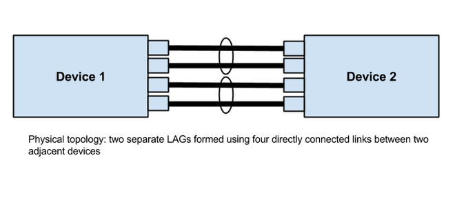
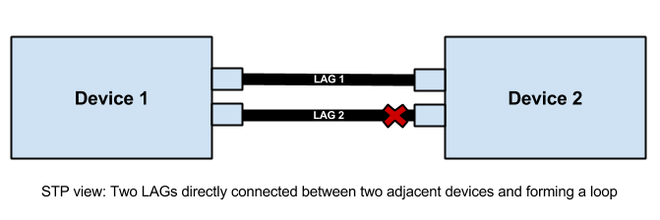
From Spanning Tree Protocol (STP) perspective, no matter how many physical ports are being used to form the LAG, there is going to be only one logical interface representing each LAG bundle. The individual ports are not part of the STP topology, but only the one logical interface. STP is still going to be active on the LAG interface and should not be turned off, so that if there are multiple LAGs configured between two adjacent nodes, STP will block one of them.
L3 LAG
While LAG is extremely common across L2 network designs, and sometimes even seen as a partial replacement for Spanning Tree Protocol (STP), it is important to mention that LAG can also operate at L3, i.e, by assigning an IPv4 or IPv6 subnet to the aggregated link. You can then setup static or dynamic routing over the LAG like any other routed interface.
LAG versus MC-LAG
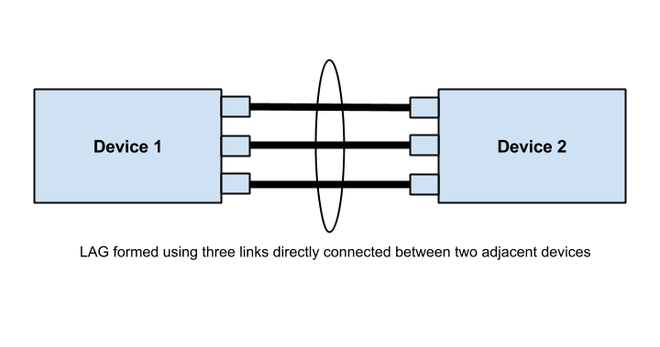
By definition, LAG is formed across two adjacent nodes which are directly connected to each other. The two nodes must be configured properly to form the LAG, so that traffic would be transferred properly between the nodes without a fear of creating traffic loops between the individual members for example.
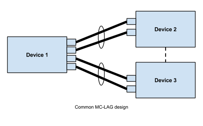
MC-LAG, or Multi-Chassis Link Aggregation Group, is a type of LAG with constituent ports that terminate on separate chassis, thereby providing node-level redundancy. Unlike link aggregation in general, MC-LAG is not covered under IEEE standard, and its implementation varies by vendor. Cisco’s vPC is a good example for a MC-LAG implementation. The real challenge with MC-LAG is to maintain a consistent control plane state across the LAG setup, which is why the various multi-chassis mechanisms insist on countermeasures such as peer links or out of band connectivity between the redundant chassis.
Load sharing operation
Traffic is not randomly placed across the LAG members, but instead shared using a deterministic hash algorithm. Depending on the platform and the configuration, a number of parameters may feed into the algorithm, including for example the ingress interface, source and/or destination MAC address, source and/or destination IP address, source and/or destination L4 (TCP/UDP) port numbers, MPLS labels, and so on.
Ultimately the hash will take in some combination of parameters to identify a flow and decide to which member link the frame should be placed in. It is important to note that all traffic for a particular flow will always be placed on the same link. That’s also means that traffic for a single flow (e.g., source and destination MAC) cannot exceed the bandwidth of a single member link. It is also important to note that each node (or chassis) performs the hash calculations locally itself, so that upstream and downstream traffic for a single flow will not necessarily traverse the same link.
Static configuration
The basic way to form a LAG is to simply specify the member ports on each node manually. This method does not involve any protocols to negotiate and form the LAG. Depending on the platform, the user can also control the hash algorithm on each side. As soon as a port becomes physically up it becomes a member of the LAG bundle. The major advantage of this is that the configuration is very simple. The disadvantage is that there is no method to detect any kind of cabling or configuration errors, which is most vendors would recommend a LACP configuration instead.
LACP configuration
LACP is the standards based protocol used to signal LAGs. It detects and protects the network from a variety of misconfiguration, ensuring that links are only aggregated into a bundle if they are consistently configured and cabled. LACP can be configured in one of two modes:
- Active mode - the device immediately sends LACP messages (LACP PDUs) when the port comes up
- Passive mode - Places a port into a passive negotiating state, in which the port only responds to LACP PDUs it receives but does not initiate LACP negotiation
If both sides are configured as active, LAG can be formed assuming successful negotiation of the other parameters. If one side is configured as active and the other one as passive, LAG can be formed as the passive port will respond to the LACP PDUs received from the active side. If both sides are passive, LACP will fail to negotiate the bundle. In practice it is rare to find passive mode used as it should be clearly and consistently defined which links will use LACP/LAG ahead of deployment. There are even vendors who does not offer the passive mode option at all.
With LACP, you can also control the timeout interval in which LACP PDUs will be sent. The standard defines two intervals: fast (1 second) and slow (30 seconds). Note that the timeout value does not have to agree between peers. While it is not a recommended configuration, it is possible to bring up a LAG with one end sending every 1 second and the other sending every 30 seconds. Depending on the platform and configuration, it is also possible to use Bidirectional Forwarding Detection (BFD) for fast detection of link failures.
Comments
No comments found for this article.
Join the discussion for this article on this issue. Comments will appear on this page instantly.